
In the first part we looked at the information about the SAM Coupe network available in the user manual, technical manual and other examples of networking systems that may have influenced the design on the SAM Coupe. Next I'm going to look at the electrical design of the SAM Coupe and the other devices, to see if they really are compatible and whether we can knock together an interface to start reading the wire protocol.
We may as well start with the only peripheral I know of that plugs into the SAM coupe Network ports: the Messenger.
Messenger
The Messenger was an MGT device which allows snapshots of software running on a ZX Spectrum to be downloaded (via the network port) to the Sam Coupe to be run there.
The full schematic by Miguel Angel Rodríguez Jódar is available on zxprojects.com. The particular bit we're interested in (optocoupler/network port) is copied below.
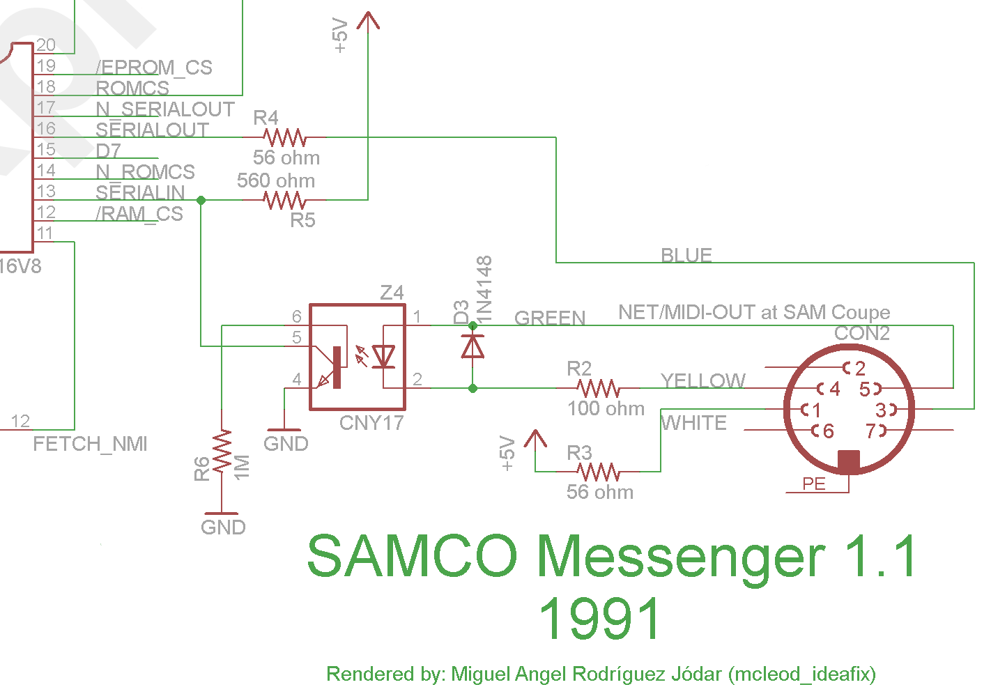
This shows pins 4 & 5 being fed into an optocoupler (serial in) and serial out coming via pin 3 & 1 (with pin 1 pulled high, not grounded). So, data from the Sam to the Messenger appears to be coming via the MIDI pins, not the network. While data from the Messenger to the Sam does use the network pins. Odd.
IDEA: This might be necessary on the Messenger because it only has a single cable, plugging into the outermost network port on the Sam.
DISCiPLE +D
As we've already looked at in the previous part, the DISCiPLE was an MGT device for the ZX Spectrum which added an easier to use disk drive and IF1-compatible networking.
The schematic (found on spdns.de) shows how the IF1 network was wired. Below is a crop from the bottom-right of the full schematic, showing the microphone-socket inputs. By default the ports are grounded, but inserting a plug latches that open, allowing the data to be read. This matches up with what we read in the ZX Interface 1 handbook – machines shouldn't be connected in a loop, as the empty sockets at each end terminate the network.
Note that receive/transmit is on the same wire – there is only one wire. Both network plugs are wired together (giving pass through) and transmission pulls this line high (+5V).
Since the Sam Coupe sockets (DIN plugs) don't have physical latches, there would need some other mechanism to terminate the network (if it's not a loop).
IDEA: I'm wondering now if cable (with the paired wires on one side) acts to un-terminate the network somehow.

To support developers in [[ countryRegion ]] I give a [[ localizedDiscount[couponCode] ]]% discount on all books and courses.
[[ activeDiscount.description ]] I'm giving a [[ activeDiscount.discount ]]% discount on all books and courses.
Sam Coupe
The full schematic (corrected) of the Sam Coupe is available from VELESOFT. The network (MIDI) part is shown below. This is a bit confusing as the pins are shown in order (1-7) rather than socket order.
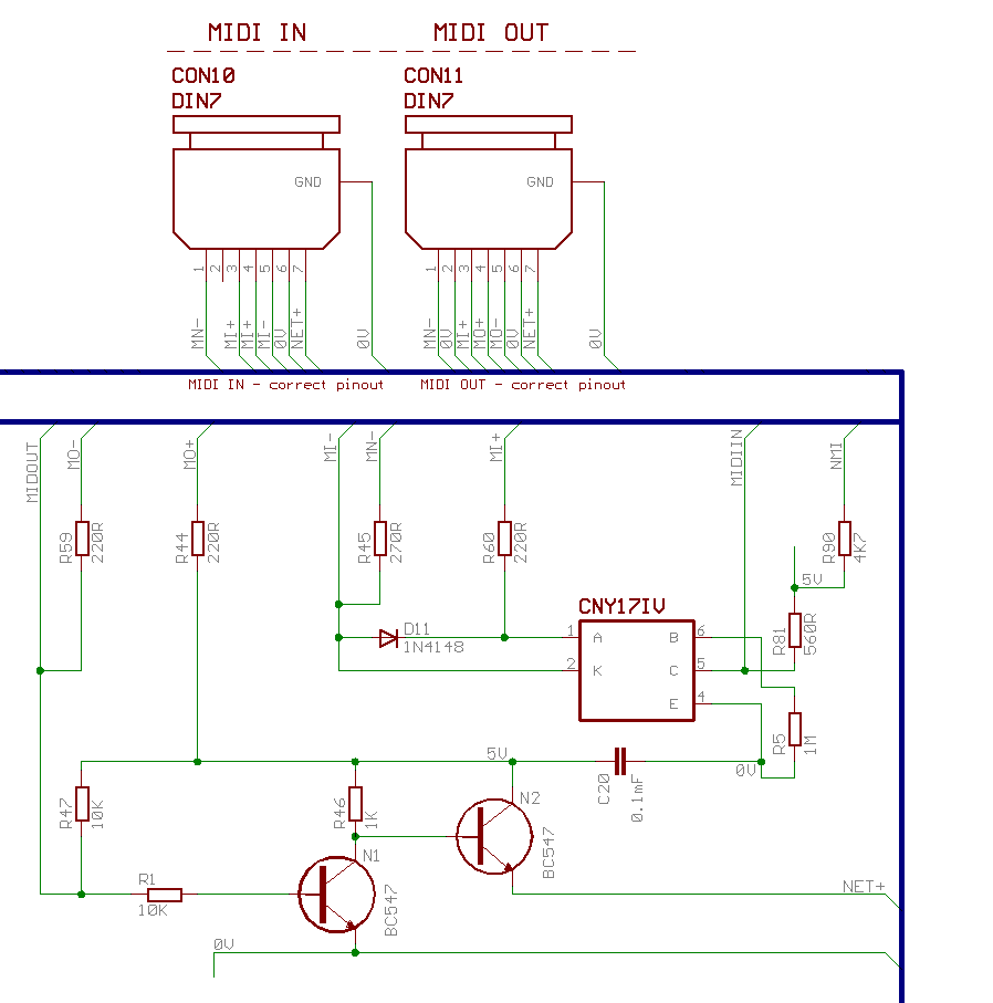
The output is driven by the line on the far left MIDOUT and input is returned to the system via the line in the top right MIDIIN. The labelling on the sockets shows that many of the pins (e.g. NET+ or MI+) are simply wired through/identical on the two sockets.
I've confirmed these connections using a multimeter.
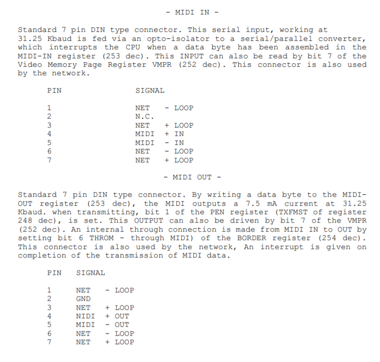
Putting the pin labels into a table with the original socket information (left from the User Manual/right schematic) we get the following listing.
| Pin | Network IN | Network OUT |
|---|---|---|
| 1 | NET- / MN-**** | NET- / MN- |
| 2 | nc | 0V |
| 3 | NET + / MI+ | NET+ / MI+ |
| 4 | MI+ | MO+ |
| 5 | MI- | MO- |
| 6 | NET - / 0V | NET- / 0V |
| 7 | NET+ / NET+ | NET+ / NET+ |
On the MIDI diagram in the User manual the let hand image was labelled MIDI OUT but there was no equivalent label on the network. Looking at the schematic we can see that MIDI and the network function identically (same circuit) just with the addition of resistors on the network side. So are the ports network IN and OUT? Not really, the wiring is identical for both ports, meaning you can use either to connect the SAM.
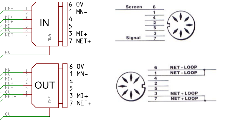 Note that this diagram doesn't show the correct socket numbering (it's backwards), do not wire your cable like this.
So, if direction is irrelevant, what is the effect of wiring together pins 6&1 and 3&7 on the network cable? An annotated version of the schematic is shown below, with NET- lines highlighted in blue (ground) and NET+ lines highlighted in red (+5V). The signal input and output are shown by the grey arrow line.
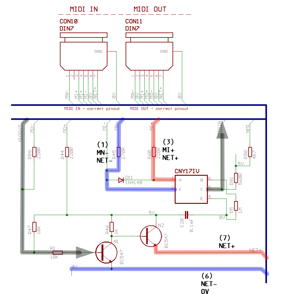
As mentioned, NET- and NET+ (pins 6&7) are wired through from one socket to another, and NET+ is driven by the computer (via MIDOUT). So, pins 6&7 are sufficient to transmit data and share it with all computers on the network, but each computer needs pins 1&3 connected (to 6&7 respectively) to be able to read the incoming data.
This makes the SamCo Messenger even weirder, since it's possible to communicate using just one network port, and MIDI & network are electrically connected why use both pins? Maybe to save a resistor in the device.
Looking at the highlighted part of the schematic, we can see that the NET+ line is pulled high by default, and pulled low (to GND) for each bit. The base of transistor N2 is connected through a resistor, to 5V, pulling it high and conducting 5V to NET+. Signal to the base of N1 opens the transistor, connecting the base of N2 to GND, switching it off.
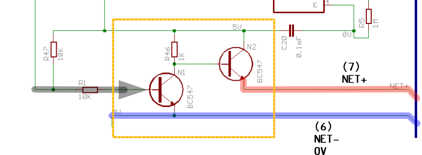
High-off, low-data is in common with standard UART data transmission, and also the standard for MIDI communication. Is the SAM network just a MIDI network?
@chipper:l@ TL;DR yes.
Network topology
Since the sockets are wired through, pins 1&3 can be connected on either socket. However, every SAM in the network needs to have those pins connected on at least one socket in order to read the data. The options for network topology are –
- loop of machines, using the cable with pins 1->6 & 3->7 wired together, each Sam getting one magic end of the cable each
- linear network, with a terminator plug on the end (one end only) which makes this connection (a dangling cable would also work)
Since I've never heard of plug terminators for the Sam Coupe, or a dangling network cable, it seems like the loop was the intended setup.
There is enough information here now to rig up a serial device and see what we can see on the net.
Based on what we've found, the SAM network looks to be using the built in MIDI support, at least electrically. The MIDI standard uses a UART connection at 31.25 Kbaud, so that would be a good place to start.
Turns out on the Atari ST it was also possible to use the MIDI network for basic networking.
In the previous part we discovered that the network data is sent on pins 6&7, and read from pins 1&3. The data is transmitted line-high, that is 5V is off and 0V is on, in keeping with UART standard. The ZX Interface 1 Wikipedia article gives us a speed of 100 kbit/s for the network, which seemed a good place to start. The Sam Coupe Technical manual lists 31.25 kbit/s for MIDI, but it's not clear if this also applies to the network (it does).
Flashing a LED, or how I found out the port numbering is backwards
To test that we can read data out of the network port I hooked up a simple circuit to the output pins on the network socket. From the schematics we know that a signal on the MIDI out pin drives our output pin high, to 5V. To see this in action we can connect a LED and resistor across this pin to ground.
It was at this point that I discovered that the diagram in the main body of the user manual has the pin order precisely backwards. The correct order is shown in the appendix.
With that fixed, we can trigger output to the network by setting the current device number of the machine with device n1 1 and then saving the current (empty) BASIC program with save "test". As you can see below, this creates two flashes on the LED.
@chipper;l Why two? We'll find out in a minute.
Moving this circuit to the other port confirmed that the MIDI in and MIDI out ports are electrically connected on the network pins. Our little dongle works just the same connected to either port -- since network out is available on the in port, we should be able to do full 2-way communication with a single port. We'll find out later if it matters which for the input.
Line specification
In the previous part we discovered that the network data is sent on pins 6&7, and read from pins 1&3. The data is transmitted line-high, that is 5V is off and 0V is on, in keeping with UART standard. The ZX Interface 1 Wikipedia article gives us a speed of 100 kbit/s for the network, which seemed a good place to start. The Sam Coupe Technical manual lists 31.25 kbit/s for MIDI, but I wasn't sure if this also applied to the network.
@chipper:l@ TL;DR it does.
Next we'll look at sending data to and from the SAM coupe from the Raspberry Pi.
-
actual network number is irrelevant as we'll discover later, this just enables network mode ↩